
D2 June 2014 (R) Q5
5.
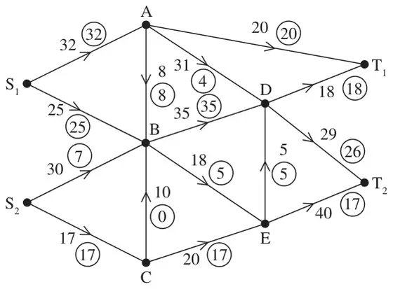
Figure 1 shows a capacitated, directed network. The number on each arc represents the capacity of that arc. The numbers in circles represent an initial flow.
| Scheme | Marks |
|---|---|
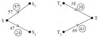 | M1 A1 A1 |
| (3) |
Notes
a1M1: Four arcs added, SS\(_1\), SS\(_2\), T\(_1\)T, T\(_2\)T and 2 numbers on each.
a1A1: CAO for arcs
a2A1: CAO for flow values and capacities
| Scheme | Marks |
|---|---|
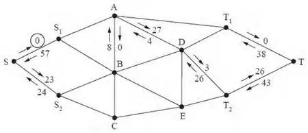 | M1 A1 |
| (2) |
Notes
b1M1: Two numbers on each arc and at least three arcs or six numbers correct.
b1A1: CAO do give bod since they might well cross these numbers out.
| Scheme | Marks |
|---|---|
| E.g. SS\(_2\)BET\(_2\)T – 13 SS\(_2\)BADT\(_2\)T – 3 SS\(_2\)BADET\(_2\)T – 5 | M1 A1 A1 A1 |
| (4) |
Notes
c1M1: One valid flow augmenting route found and a value stated.
c1A1: Flow increased by at least 3.
c2A1: A second correct flow route of value at least 5 and value correct.
c3A1: CSO Flow increased by 21 and no more.
| Scheme | Marks |
|---|---|
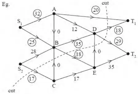 | M1 A1 |
| (2) |
Notes
d1M1: Consistent flow pattern \(\geqslant\) 84 (check each node). One number only per arc. No unnumbered arcs.
d1A1: CAO, showing flow of 102, must follow from their routes.
| Scheme | Marks |
|---|---|
| The cut through AT\(_1\), DT\(_1\), DT\(_2\), DE, BE, CB and S\(_2\)C has value 102 | DB1 |
| Value of the flow is 102 so by max flow – min cut theorem flow is maximal | DB1 |
| (2) | |
| 13 marks |
Notes
e1DB1: Must have attempted (d) - at least one number on all but one arc, and made an attempt at a cut, either drawn or stated.
e2DB1: CSO - (d) fully correct (showing a correct flow of 102) and a correct cut. Must refer to max flow-min cut theorem – all four words.