
D2 June 2015 Q4
4.
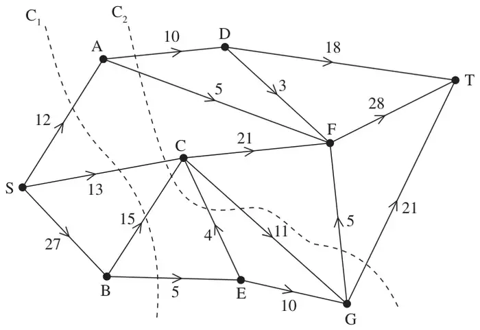
Figure 1 shows a capacitated network. The capacity of each arc is shown on the arc. Two cuts C\(_1\) and C\(_2\) are shown.
(a) Find the capacity of each of the two cuts. (2)
Given that one of these two cuts is a minimum cut,
(b) write down the maximum possible flow through the network. (1)
Given that the network now has a maximal flow from S to T,
(c) determine the flow along arc SB. (1)
(d) Explain why arcs GF and GT cannot both be saturated. (1)
Given that arcs EC, AD and DF are saturated and that there is no flow along arc GF,
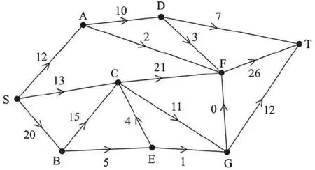
(e) determine a maximum flow pattern for this network and draw it on Diagram 1 in the answer book. You do not need to use the labelling procedure to determine the maximum flow. (2)
| Scheme | Marks |
|---|---|
| \(C_1 = 45,\ C_2 = 73\) | B1 B1 |
| (2) |
Notes
a1B1: CAO for \(C_1\) (45)
a2B1: CAO for \(C_2\) (73)
| Scheme | Marks |
|---|---|
| 45 | B1ft |
| (1) |
Notes
b1B1ft: 45 or the value of their smallest cut from (a)
| Scheme | Marks |
|---|---|
| 20 | B1 |
| (1) |
Notes
c1B1: CAO (20)
| Scheme | Marks |
|---|---|
| The maximum capacity of the arcs flowing into G is 21 and so both GF and GT cannot be full to capacity as the capacity of the arcs flowing out of G is 26 | B1 |
| (1) |
Notes
d1B1: CAO – argument must be numerical in nature (as a minimum accept 26 > 21 (oe))
| Scheme | Marks |
|---|---|
 | M1 A1 |
| (2) | |
| 7 marks |
Notes
e1M1: Consistent flow pattern – check each node, must have exactly 1 number per arc (arc EC must be 4, AD – 10 and DF – 3 but all other arcs may have over-capacatiated values)
e1A1: CAO