
D2 June 2013 (R) Q6
6.
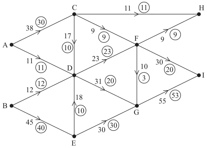
Figure 1 shows a capacitated directed network. The number on each arc represents the capacity of that arc. The numbers in circles represent an initial flow.
| Scheme | Marks |
|---|---|
| Initial flow = 93 | B1 |
| (1) |
Notes
a1B1: CAO
| Scheme | Marks |
|---|---|
| Adds supersource S plus arcs SA(49) and SB(57) | M1 |
| Adds supersink T plus arcs HT(20) and IT(85) | A1 |
| (2) |
Notes
b1M1: All relevant arcs added OR all arcs and numbers from supersource OR from supersink correct.
b1A1: CAO all arcs and numbers correct.
| Scheme | Marks |
|---|---|
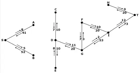 | M1 A1 A1 |
| (3) |
Notes
c1M1: 2 numbers and arrows on each arc.
c1A1: CAO Condone 4 errors.
c2A1: CAO.
| Scheme | Marks |
|---|---|
| E.g. SACDGIT – 2 and SACDGFIT – 3 | M1 A1 |
| Maximum flow = 98 | A1 |
| (3) |
Notes
d1M1: One valid flow augmenting route (from S to T) found and a value stated.
d1A1: Flow increased by 5 and no more.
d2A1: CAO 98 (allow if seen in (f) but must be clearly labelled as the maximum flow)
Examples of flow augmenting routes:
- SACDGFIT (3), SACDGIT (2)
- SBEDGFIT (3), SBEDGIT (2)
- SBEDGFIT (3), SACDGIT (2)
- SACDGFIT (3), SBEDGIT (2)
| Scheme | Marks |
|---|---|
E.g.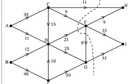 | M1 A1 |
| (2) |
Notes
e1M1: Consistent flow pattern > 95 – condone S and T’s presence. Must have exactly one number on each arc.
e1A1: CAO must follow from their routes (allow if routes in (d) do not include S and/or T).
| Scheme | Marks |
|---|---|
| Max flow = min cut, cut through CH, CF, DF, FG, GI | M1 A1 |
| (2) | |
| 13 marks |
Notes
f1M1: Must have attempted (e) and made an attempt at a cut.
f1A1: cut correct – may be drawn. Must have shown a correct flow of 98 in (e). Refer to max flow-min cut theorem all four words.