
D2 June 2009 Q4
4.
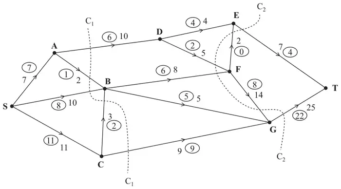
Figure 1 shows a capacitated network. The capacity of each arc is shown on the arc. The numbers in circles represent an initial flow from S to T.
Two cuts C\(_1\) and C\(_2\) are shown in Figure 1.
(a) Find the capacity of each of the two cuts. (2)
(b) Find the maximum flow through the network. You must list each flow-augmenting route you use together with its flow. (3)
| Scheme | Marks |
|---|---|
| Value of cut C\(_1\) = 34; Value of cut C\(_2\) = 45 | B1; B1 |
| (2) |
Notes
1B1: cao
2B1: cao
| Scheme | Marks |
|---|---|
| S B F G T or S B F E T – value 2 | M1 A1 |
| Maximum flow = 28 | A1=B1 |
| (3) | |
| (5 marks) |
Notes
1M1: feasible flow-augmenting route and a value stated
1A1: a correct flow-augmenting route and value
1A1= B1: cao