
D2 June 2010 Q5
5.
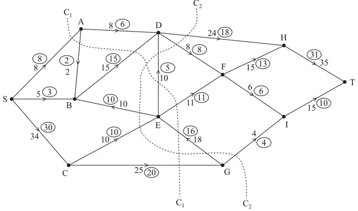
Figure 2 shows a capacitated, directed network. The number on each arc represents the capacity of that arc. The numbers in circles represent an initial flow.
(a) State the value of the initial flow. (1)
(b) State the capacities of cuts C\(_1\) and C\(_2\). (2)
(c) By entering values along DH, FH, FI and IT, complete the labelling procedure on Diagram 1 in the answer book. (2)
(d) Using Diagram 1, increase the flow by a further 4 units. You must list each flow-augmenting route you use, together with its flow. (3)
(e) Prove that the flow is now maximal. (2)
| Scheme | Marks |
|---|---|
| Initial flow = 41 | B1 |
| (1) |
Notes
1B1: cao
| Scheme | Marks |
|---|---|
| Capacity of C\(_1\) = 69 | B1 |
| Capacity of C\(_2\) = 64 | B1 |
| (2) |
Notes
1B1: cao (permit B1 if 2 correct answers, but transposed)
2B1: cao
| Scheme | Marks |
|---|---|
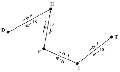 | M1 A1 |
| (2) |
Notes
1M1: Two numbers on each arc
1A1: cao
| Scheme | Marks |
|---|---|
| e.g. SBADHT – 2 | M1 A1 |
| SCGEDHT – 2 | A1 |
| (3) |
Notes
1M1: One valid flow augmenting route, S to T, found and value (\(\leqslant 4\)) stated.
1A1: Flow increased by at least 2
2A1: Flow increased by 4
| Scheme | Marks |
|---|---|
| maximum flow = minimum cut | DM1 |
| e.g. cut through SA, SB, CE, GE, GI or HT, FI, GI | A1 |
| (2) | |
| (10 marks) |
Notes
1DM1: Must have attempted (d) and made an attempt at a cut.
1A1: cut correct – may be drawn. Refer to max flow-min cut theorem three words out of four.