
D1 June 2008 Q5
5.
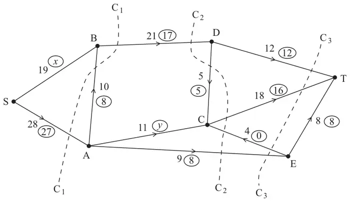
Figure 5 shows a capacitated, directed network of pipes. The number on each arc represents the capacity of that pipe. The numbers in circles represent a feasible flow.
(a) State the values of \(x\) and \(y\). (2)
(b) List the saturated arcs. (2)
(c) State the value of the feasible flow. (1)
(d) State the capacities of the cuts \(\text{C}_1\), \(\text{C}_2\), and \(\text{C}_3\). (3)
(e) By inspection, find a flow-augmenting route to increase the flow by one unit. You must state your route. (1)
(f) Prove that the new flow is maximal. (2)
| Scheme | Marks |
|---|---|
| \(x = 9,\ \ y = 11\) | B1, B1 |
| (2) |
Notes
(a) 1B1: cao (permit B1 if 2 correct answers, but transposed)
2B1: cao
| Scheme | Marks |
|---|---|
| AC DC DT ET | B2, 1, 0 |
| (2) |
Notes
(b) 1B1: correct (condone one error – omission or extra)
2B1: all correct (no omissions or extras)
| Scheme | Marks |
|---|---|
| 36 | B1 |
| (1) |
Notes
(c) 1B1: cao
| Scheme | Marks |
|---|---|
| \(\text{C}_1 = 49,\ \ \text{C}_2 = 48,\ \ \text{C}_3 = 39\) | B1, B1, B1 |
| (3) |
Notes
(d) 1B1: cao
2B1: cao
3B1: cao
| Scheme | Marks |
|---|---|
| e.g. SAECT | B1 |
| (1) |
Notes
(e) 1B1: A correct route (flow value of 1 given)
| Scheme | Marks |
|---|---|
| maximum flow = minimum cut cut through DT, DC, AC and AE | M1 A1 |
| (2) | |
| (11 marks) |
Notes
(f) 1M1: Must have attempted (e) and made an attempt at a cut.
1A1: cut correct – may be drawn. Refer to max flow-min cut theorem three words out of four.