
A2 October 2020 Q5
5.
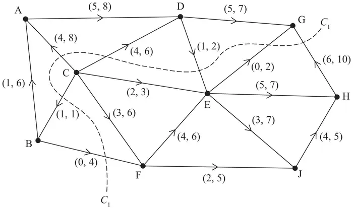
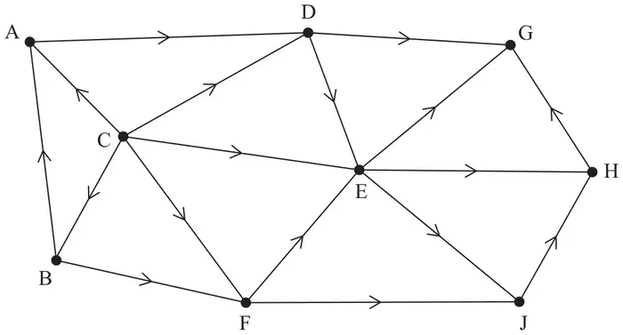
Figure 2 shows a capacitated, directed network. The network represents a system of pipes through which fluid can flow.
The weights on the arcs show the lower capacities and upper capacities for the corresponding pipes, in litres per second.
| Scheme | Marks | AO |
|---|---|---|
| Source node is C | B1 | 1.1b |
| (1) |
Notes
B1: cao (node C)
| Scheme | Marks | AO |
|---|---|---|
| G is the sink node as all the arcs incident to G flow into G | B1 | 2.4 |
| (1) |
Notes
B1: correct explanation of why G is the sink node
| Scheme | Marks | AO |
|---|---|---|
| Capacity of cut \(C_1 = 10 + 2 - 1 + 6 + 8 + 1 - 0 = 26\) | B1 | 1.1b |
| (1) |
Notes
B1: cao
| Scheme | Marks | AO |
|---|---|---|
| (i) Arc JH must be at its upper capacity of 5 as the two arcs that flow into J (EJ and FJ) have a lower capacity of \(2 + 3 = 5\) | B1 | 2.4 |
| (ii) Arcs AD and CD must be at the lower capacities (which in total is 9) as the only two arcs (DG and DE) that flow out of D have a total upper capacity of \(7 + 2 = 9\) | B1 | 2.4 |
| (2) |
Notes
(d)(i) B1: correct explanation that JH must be at its upper capacity (must refer to arcs EJ and FJ)
(d)(ii) B1: correct explanation that AD and CD must be at their lower capacities (must refer to arcs DG and DE)
| Scheme | Marks | AO |
|---|---|---|
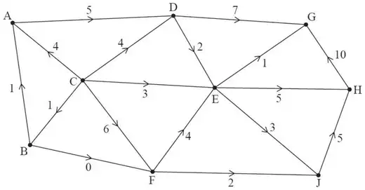 | M1 A1 | 2.2a 1.1b |
| (2) |
Notes
M1: ‘flow in = flow out’ at all but one vertex – one number only required on each arc (condone blank for arc BF)
A1: a correct valid flow through the network (check that flow in must equal flow out at each vertex)
| Scheme | Marks | AO |
|---|---|---|
| Use of max-flow min-cut theorem | M1 | 2.1 |
| Identification of cut through DG, DE, CE, CF, CB, BA with a capacity of 18 and value of flow = 18 | A1 | 3.1a |
| Therefore it follows that flow is maximal | A1 | 2.2a |
| (3) | ||
| (10 marks) |
Notes
M1: Construct argument based on max-flow min-cut theorem (e.g. attempt to find a cut through saturated arcs)
A1: Use appropriate process of finding a minimum cut (cut + value correct)
A1: Correct deduction that the flow is maximal