
A2 June 2024 Q1
1.
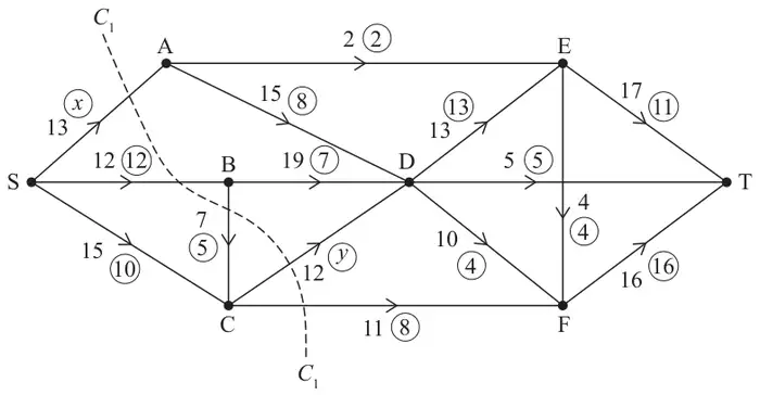
Figure 1 shows a capacitated, directed network of pipes. The numbers in circles represent an initial flow from S to T. The other number on each arc represents the capacity, in litres per second, of the corresponding pipe.
You must state your route. (1)
The flow-augmenting route from (d) is used to increase the flow from S to T.
A vertex restriction is now applied so that no more than 12 litres per second can flow through E.
| Scheme | Marks | AO |
|---|---|---|
| (i) \(x = 10\) | B1 | 1.1b |
| (ii) \(y = 7\) | B1 | 1.1b |
| (2) |
Notes
B1: CAO for \(x\)
B1: CAO for \(y\)
| Scheme | Marks | AO |
|---|---|---|
| 32 | B1 | 1.1b |
| (1) |
Notes
B1: CAO
| Scheme | Marks | AO |
|---|---|---|
| Cut \(C_1\,(= 13 + 12 + 12 + 11) = 48\) | B1 | 1.1b |
| (1) |
Notes
B1: CAO
| Scheme | Marks | AO |
|---|---|---|
| SCDFET | B1 | 1.1b |
| (1) |
Notes
B1: CAO
| Scheme | Marks | AO |
|---|---|---|
| Use of max-flow min-cut theorem Identification of cut through AE, DE, DT, EF and FT Value of flow = 36 It follows that flow is maximal | M1 A1 A1 | 2.1 3.1a 2.2a |
| (3) |
Notes
M1: Construct argument based on max-flow min-cut theorem (e.g. attempt to find a cut through saturated arcs). The cut may be drawn or stated in terms of arcs but not as nodes. (Note the only saturated arc not in the cut is SB)
A1: Use appropriate process of finding a minimum cut: cut + value correct
dA1: Must have stated the value of the flow and correct deduction that the flow is maximal. Must use max flow = min cut all 4 words dependent on previous A mark so M1 A0 A1 is not possible
| Scheme | Marks | AO |
|---|---|---|
(i)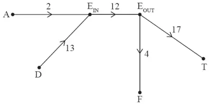 | B1 | 3.3 |
| (ii) maximum flow = 33 | B1ft | 2.2a |
| (2) | ||
| (10 marks) |
Notes
B1: Flows into E go to EIN and flows out of E go from EOUT and arc of capacity 12 from EIN to EOUT All arcs must have the correct arrow and capacity shown. Split node must be labelled as EIN and EOUT or E1 and E2
B1ft: Value of their maximum flow – 3