
AS June 2025 Q2
2.
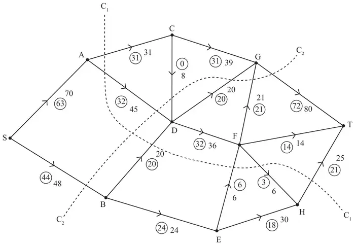
Figure 1 shows a capacitated, directed network of pipes. The number on each arc represents the capacity of the corresponding pipe. The numbers in circles represent a feasible flow from S to T.
| Scheme | Marks | AO |
|---|---|---|
| On every arc actual flow cannot exceed capacity. Total flow into a vertex equals total flow out of the vertex for all vertices apart from the source and the sink. | B1 B1 | 1.2 1.2 |
| (2) |
Notes
a1B1: Either condition.
a2B1: Both conditions (condone no mention of source and sink).
| Scheme | Marks | AO |
|---|---|---|
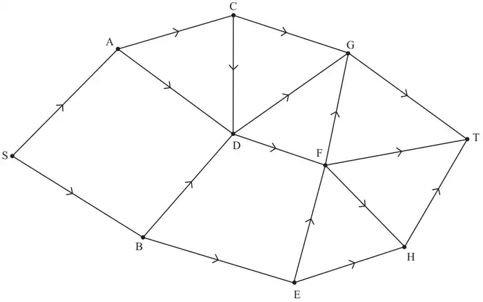
| AC, BD, BE, DG, EF, FG, FT | B1 | 1.1b |
| (1) |
Notes
b1B1: CAO
| Scheme | Marks | AO |
|---|---|---|
| (i) \(C_1 = (31 + 45 + 20 + 6 + 25 =)\ 127\) | B1 | 1.1b |
| (ii) \(C_2 = (80 + 8 + 45 + 48 =)\ 181\) | B1 | 1.1b |
| (2) |
Notes
ci1B1: CAO
cii1B1: CAO
| Scheme | Marks | AO |
|---|---|---|
| SADFEHT | B1 | 1.1b |
| (1) |
Notes
d1B1: A correct flow-augmenting route.
| Scheme | Marks | AO |
|---|---|---|
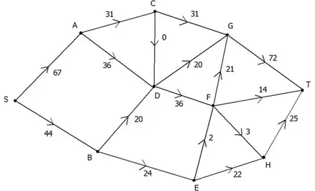 | M1 A1 | 1.1b 1.1b |
| (2) |
Notes
e1M1: All arcs labelled with flows, condone two errors. Condone capacity as well (if clearly distinguished) for this mark
e1A1: Correct numbers labelled on all arcs (one number per arc)
| Scheme | Marks | AO |
|---|---|---|
| Use of max-flow min-cut theorem Identifies cut through, AC, DC, DG, DF, BE or AC, CD, DG, FG, FT, HT capacity = 111 Value of flow =111 Therefore flow is maximal. | M1 A1 A1 | 2.1 3.1a 2.2a |
| (3) | ||
| (11 marks) |
Notes
f1M1: Construct argument based on max-flow min-cut theorem so attempt to find a cut through saturated arcs (either stated or drawn).
f1A1: Use appropriate process for finding minimum cut, with cut and value correct.
f2A1: Correct deduction that flow is maximal. Must state value of the flow and see all 4 words max flow min cut and conclusion