
AS June 2019 Q3
3.
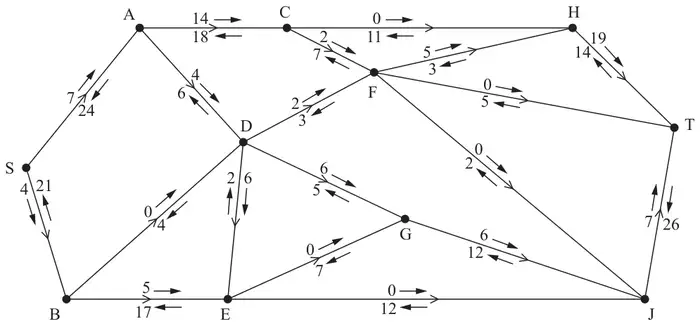
Alexa is monitoring a system of pipes through which fluid can flow from the source, S, to the sink, T. Currently, fluid is flowing through the system from S to T.
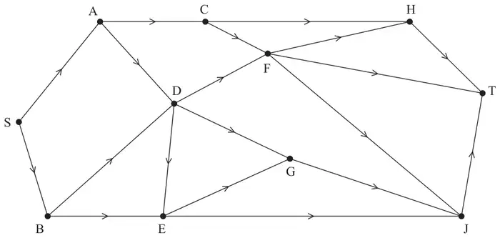
Alexa initialises the labelling procedure for this system, and the excess capacities and potential backflows are shown on the arrows either side of each arc, as shown in Figure 1.
| Scheme | Marks | AO |
|---|---|---|
| 45 | B1 | 1.1b |
| (1) |
Notes
B1: CAO (45)
| Scheme | Marks | AO |
|---|---|---|
| e.g. the total capacity of arcs DF and DG is 5 + 11 = 16. The capacity of the two arcs leading into D are 10 (from AD) and 4 (from BD) giving a total capacity into D of 14. As 14 < 16 arcs DF and DG cannot both be full to capacity | B1 | 2.4 |
| (1) |
Notes
B1: CAO (as a minimum accept mention that the max flow into D is 14 and max flow out of D is 16 together with comparison of these two values – (node) D must be mentioned)
| Scheme | Marks | AO |
|---|---|---|
| Value of cut = 32 + 10 + 4 + 7 + 12 = 65 | B1 | 1.1b |
| (1) |
Notes
B1: CAO (65)
| Scheme | Marks | AO |
|---|---|---|
| e.g. SACFHT – 2; SADGJT – 4; SBEDFHT – 2 e.g. SACFHT – 2; SADGJT – 2; SADFHT – 2; SBEDGJT – 2 e.g. SACFHT – 2; SADGJT –4; SBEDGJT – 2 | M1 A1 A1 | 1.1b 1.1b 1.1b |
| (3) |
Notes
M1: One correct flow augmenting route found from S to T + flow value or two correct routes
A1: Two correct routes + correct flow values
A1: CSO – increasing the flow by 8 only
| Scheme | Marks | AO |
|---|---|---|
e.g.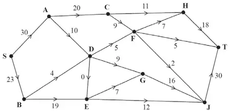 DF 3, FH 5, HT 16 | B1 | 1.1b |
| (1) |
Notes
B1: CAO – condone more than one value on an arc only if one of these values is circled – mark those that have been circled only
| Scheme | Marks | AO |
|---|---|---|
| Use of max-flow min-cut theorem Identification of cut through CH, CF, AD, BD, DE, EG and EJ Value of flow = 53 Therefore by the max-flow min-cut theorem it follows that flow is maximal | M1 A1 A1 | 2.1 3.1a 2.2a |
| (3) | ||
| (10 marks) |
Notes
M1: Construct the start of an argument based on the max-flow min-cut theorem (that is an attempt to find a genuine cut together with the value of either their cut or flow (but not re-iterating the cut given in (c) – AC, AD, BD, DE, EG, EJ))
A1: Use appropriate process of finding a minimum cut – must see correct cut + value correct (accept ‘53’ and the cut either stated or drawn on either diagram)
A1: Correct deduction that the flow is maximal by stating ‘maximum flow (equal to) minimum cut’ – dependent on previous A mark and the correct flow in (e)