
D1 June 2005 Q8
8.
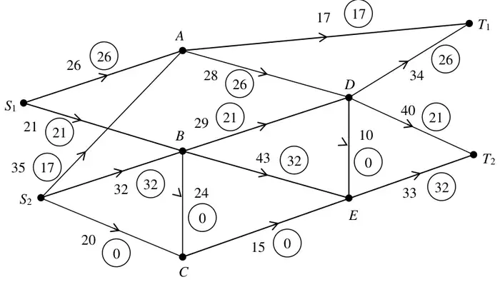
Figure 6 shows a capacitated directed network. The number on each arc is its capacity. The numbers in circles show a feasible flow through the network. Take this as the initial flow.
(a) On Diagram 1 and Diagram 2 in the answer book, add a supersource \(S\) and a supersink \(T\). On Diagram 1 show the minimum capacities of the arcs you have added. (2)
Diagram 2 in the answer book shows the first stage of the labelling procedure for the given initial flow.
(b) Complete the initial labelling procedure in Diagram 2. (2)
(c) Find the maximum flow through the network. You must list each flow-augmenting route you use, together with its flow, and state the maximal flow. (6)
(d) Show a maximal flow pattern on Diagram 3. (2)
(e) Prove that your flow is maximal. (2)
(f) Describe briefly a situation for which this network could be a suitable model. (2)
| Scheme | Marks |
|---|---|
| \(SS_1 - 47,\ SS_2 - 87,\ T_1T - 51,\ T_2T - 73\) added to diagram 1 | M1 A1 |
| (2) |
| Scheme | Marks |
|---|---|
| \(SS_1\ \begin{smallmatrix}\rightarrow 0\\ \leftarrow 47\end{smallmatrix},\quad SS_2\ \begin{smallmatrix}\rightarrow 38\\ \leftarrow 49\end{smallmatrix},\quad T_1T\ \begin{smallmatrix}\rightarrow 8\\ \leftarrow 43\end{smallmatrix},\quad T_2T\ \begin{smallmatrix}\rightarrow 20\\ \leftarrow 53\end{smallmatrix}\) | M1 A1 |
| (2) |
| Scheme | Marks |
|---|---|
| e.g. \(SS_2ADT_1T - 2\) \(SS_2CET_2T - 1\) \(SS_2CEDT_2T - 10\) \(SS_2CEBDT_1T - 4\) | M1 A4,3,2,1,0 |
| maximum flow – 113 | B1 |
| (6) |
Notes
The B1 for the maximum flow is linked in the scheme to the M1 in (e).
| Scheme | Marks |
|---|---|
e.g.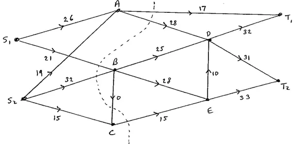 | M1 A1 |
| (2) |
| Scheme | Marks |
|---|---|
| max flow – min cut theorem; cut \(AT_1, AD, S_1B, S_2B, BC, CE\) | M1 A1 |
| (2) |
| Scheme | Marks |
|---|---|
| Idea of a directed flow along arcs; from \(S\) to \(T\); through a system; practical network | B2,1,0 |
| (2) | |
| (16 marks) |