
D1 January 2005 Q6
6.
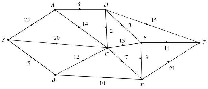
Figure 4 shows a capacitated directed network. The number on each arc is its capacity.
(a) State the maximum flow along
(i) \(SADT\),
(ii) \(SCET\),
(iii) \(SBFT\). (2)
(b) Show these maximum flows on Diagram 1 in the answer book. (1)
Take your answer to part (b) as the initial flow pattern.
(c)
(i) Use the labelling procedure to find a maximum flow from \(S\) to \(T\). Your working should be shown on Diagram 2 in the answer book. List each flow-augmenting route you use, together with its flow. (5)
(ii) Draw your final flow pattern on Diagram 3 in the answer book. (2)
(iii) Prove that your flow is maximal. (3)
(d) Give an example of a practical situation that could have been modelled by the original network. (1)
| Scheme | Marks |
|---|---|
| \(SADT - 8\quad SCET - 11\quad SBFT - 9\) | B2,1,0 |
| Scheme | Marks |
|---|---|
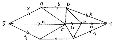 | B1 |
| (3) |
Notes
The (3) covers parts (a) and (b).
| Scheme | Marks |
|---|---|
(i)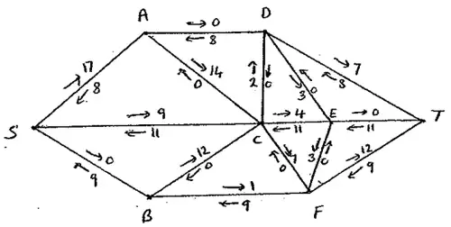 | M1 A1 (2) |
| e.g. \(SACDT - 2\qquad SCFT - 6\) | A1 |
| \(SACEFT - 3\qquad SACFT - 1\qquad\) max flow 40 | A1 A1 (3) |
(ii) e.g.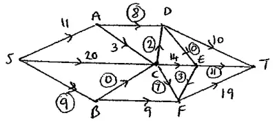 | M1 A1 (2) |
| (iii) Max flow – min cut theorem cut \(AD, CD, DE, ET, EF, CF, BC, SB\) i.e. \(\{S\,A\,C\,E\}\ \{B\,D\,F\,T\}\) | M1 A2,0 (3) |
| Scheme | Marks |
|---|---|
| Idea of a directed flow through a system of arcs from \(S\) to \(T\) practical | B1 |
| (1) | |
| (14 marks) |