
A2 June 2023 Q1
1.
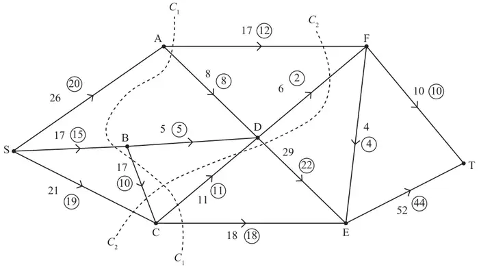
Figure 1 shows a capacitated, directed network of pipes. The number on each arc represents the capacity of that pipe. The numbers in circles represent a feasible flow from S to T.
| Scheme | Marks | AO |
|---|---|---|
| 54 | B1 | 1.1b |
| (1) |
Notes
B1: CAO
| Scheme | Marks | AO |
|---|---|---|
| \(C_1\,(= 17 + 8 + 17 + 11 + 18) = 71\) \(C_2\,(= 17 + 6 + 29 + 17 + 21) = 90\) | B1 B1 | 1.1b 1.1b |
| (2) |
Notes
B1: CAO for \(C_1\)
B1: CAO for \(C_2\)
| Scheme | Marks | AO |
|---|---|---|
| SAFDET | B1 | 1.1b |
| (1) |
Notes
B1: CAO
| Scheme | Marks | AO |
|---|---|---|
| Use of max-flow min-cut theorem Identification of cut through FT, FE, DF, AD, BD, CD and CE Value of flow = 56 Therefore it follows that flow is maximal | M1 A1 A1 | 2.1 3.1a 2.2a |
| (3) | ||
| (7 marks) |
Notes
M1: Construct argument based on max-flow min-cut theorem (e.g. attempt to find a cut through arcs – must contain source on one side and sink on the other). Allow a cut drawn on the diagram (need not be the correct one). If cut not drawn, must list arcs not values.
A1: Use appropriate process of finding a minimum cut – FT, FE, DF, AD, BD, CD and CE plus value correct and value of flow through the network stated correctly (56)
A1: Correct deduction that the flow is maximal – must use all four words ‘maximum’, ‘flow’, ‘minimum’ and ‘cut’ (allow use of max and min) dependent on previous A1.