
D2 June 2011 Q5
5.
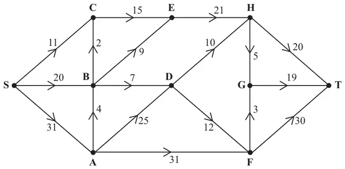
Figure 2 shows a capacitated directed network. The number on each arc is its capacity.
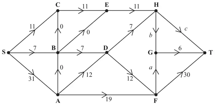
Figure 3 shows an initial flow through the same network.
(a) State the values of flows \(a\), \(b\) and \(c\), and the value of the initial flow. (4)
(b) By entering values along HG, HT and FG, complete the labelling procedure on Diagram 1 in the answer book. (2)
(c) Find the maximum flow through the network. You must list each flow-augmenting route you use, together with its flow. (4)
(d) State the value of the maximum flow through the network. (1)
(e) Show your maximum flow on Diagram 2 in the answer book. (2)
(f) Prove that your flow is maximal. (2)
| Scheme | Marks |
|---|---|
| \(a = 1\quad b = 5\quad c = 13\quad\) Flow = 49 | B1, B1, B1, B1 |
| (4) |
Notes
1B1: \(a = 1\) cao
2B1: \(b = 5\) cao
3B1: \(c = 13\) cao
4B1: 49 cao
| Scheme | Marks |
|---|---|
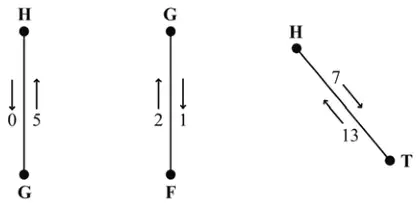 | M1 A1 |
| (2) |
Notes
1M1: Two numbers on each arc
1A1: cao
| Scheme | Marks |
|---|---|
| e.g. SBEHT - 7 together with either SBEHDAFGT – 2 or SBCEHDAFGT - 2 | M1 A1 A2,1,0 |
| (4) |
Notes
1M1: One valid flow augmenting route found and value stated.
1A1: Flow increased by at least 2
2A1: A second correct flow
3A1: Flow increased by 9 and no more
| Scheme | Marks |
|---|---|
| 58 | B1 |
| (1) |
Notes
1B1: cao
| Scheme | Marks |
|---|---|
e.g.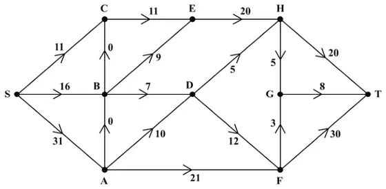 | M1 A1 |
| (2) |
Notes
1M1: Consistent flow pattern > 51
1A1: cao
| Scheme | Marks |
|---|---|
| Max flow = min cut Cut through HT, HG, GF, FT Value 58 | M1 A1 |
| (2) | |
| (15 marks) |
Notes
1M1: Must have attempted (e), S to T, and made an attempt at a cut.
1A1: cut correct – may be drawn. Refer to max flow-min cut theorem three words out of four.