
D1 June 2006 Q7
7.
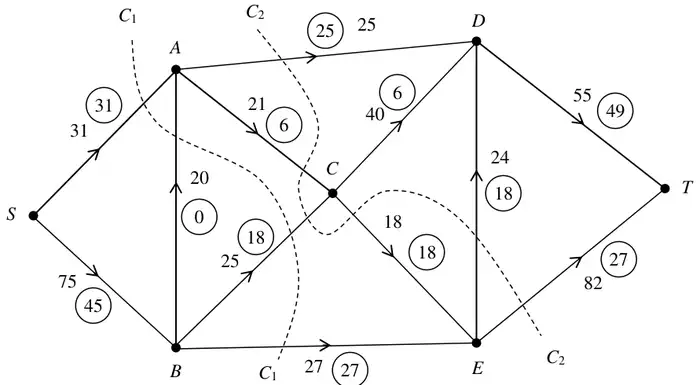
Figure 5 shows a capacitated, directed network. The capacity of each arc is shown on each arc. The numbers in circles represent an initial flow from \(S\) to \(T\).
Two cuts \(C_1\) and \(C_2\) are shown on Figure 5.
(a) Write down the capacity of each of the two cuts and the value of the initial flow. (3)
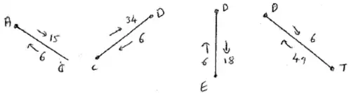
(b) Complete the initialisation of the labelling procedure on Diagram 1 by entering values along arcs \(AC\), \(CD\), \(DE\) and \(DT\). (2)
(c) Hence use the labelling procedure to find a maximal flow through the network. You must list each flow-augmenting path you use, together with its flow. (5)
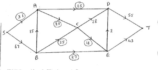
(d) Show your maximal flow pattern on Diagram 2. (2)
(e) Prove that your flow is maximal. (2)
| Scheme | Marks |
|---|---|
| \(C_1 = 103,\quad C_2 = 177,\quad\) flow \(= 76\) | B1, B1, B1 |
| (3) |
Notes
B1 103 cao
B1 177 cao
B1 76 cao
| Scheme | Marks |
|---|---|
 | M1 A1 |
| (2) |
Notes
M1 2 numbers added to each of the 4 arcs
A1 cao
| Scheme | Marks |
|---|---|
| e.g. \(SBCDT - 6\) \(SBCDET - 1\) \(SBACDET - 15\) | M1 A3,2,1,0 |
| max. flow is 98 | B1 |
| (5) |
Notes
M1 1 correct route + flow found (flow > 15 gets M0) (condone initial flow augmenting routes only if clearly separated from the rest)
A3 all routes + flows found to 22 more
A2 2 routes + flows found to 12+
A1 1 route + flow found to 6+
B1 98 cao (linked in the scheme to the M1 in (e))
| Scheme | Marks |
|---|---|
 | M1 A1 |
| (2) |
Notes
M1 Consistent flow of 77+, complete, clear (doesn’t need to ft from (c))
A1 c.a.o.
| Scheme | Marks |
|---|---|
| maximum flow = minimum cut cut through \(AD, AC, BC\) and \(BE\) | M1 A1 |
| (2) | |
| (14 marks) |
Notes
M1 Flow of 98 + cut attempted + max flow min cut theorem referred to (3 out of 4)
A1 cao