
A2 October 2021 Q5
5.
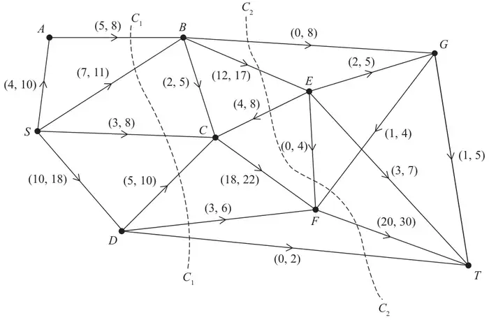
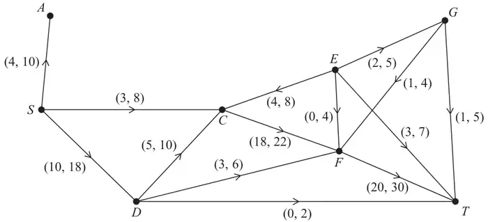
Figure 1 shows a capacitated, directed network. The network represents a system of pipes through which fluid can flow.
The weights on the arcs show the lower and upper capacities for the corresponding pipes, in litres per second.
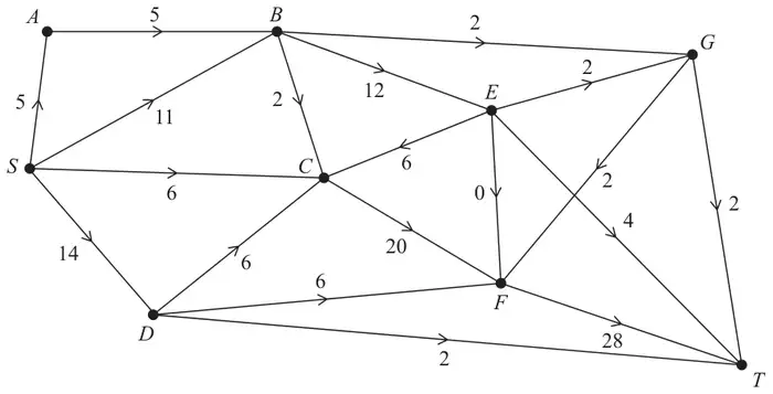
Figure 2 shows an initial flow through the same network.
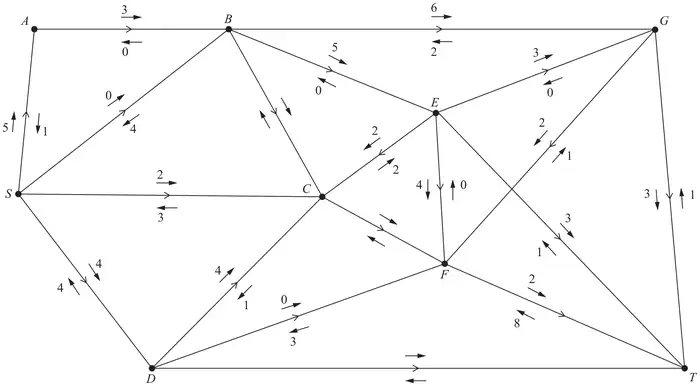
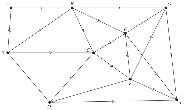
A vertex restriction is now applied to \(B\) so that no more than 16 litres per second can flow through it.
| Scheme | Marks | AO |
|---|---|---|
| (i) \(C_1 = 8 + 11 + 8 + 10 + 6 + 2 = 45\) (ii) \(C_2 = 8 + 17 - 4 - 0 - 1 + 30 + 2 = 52\) | B1 B1 | 1.1b 1.1b |
| (2) |
Notes
(i) B1: cao
(ii) B1: cao
| Scheme | Marks | AO |
|---|---|---|
| Deduces the maximum possible flow is \(\leqslant 45\) litres per second | B1ft | 2.2a |
| (1) |
Notes
B1ft: Deduced from their least value given in (a) - must include ‘less than or equal to’ (oe)
| Scheme | Marks | AO |
|---|---|---|
| Initial flow = 36 | B1 | 1.1b |
| (1) |
Notes
B1: cao
| Scheme | Marks | AO |
|---|---|---|
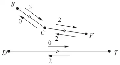 | M1 A1 | 1.1b 1.1b |
| (2) |
Notes
M1: Two numbers on each arc and at least two arcs or four numbers correct (so correct numbers with the correct arrows)
A1: cao do give bod since they might well cross these numbers out
| Scheme | Marks | AO |
|---|---|---|
| e.g., SABGT – 2, SCFT – 2, SDCET – 2, SABET – 1 e.g., SABGT – 3, SCFT – 2, SDCET – 2 | M1 A1 A1 | 1.1b 1.1b 1.1b |
| (3) |
Notes
M1: One flow augmenting route found from S to T
A1: Two correct routes + flow values
A1: cso – increasing the flow by 7
| Scheme | Marks | AO |
|---|---|---|
e.g.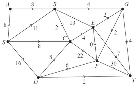 | B1 | 2.2a |
| (1) |
Notes
B1: cao
| Scheme | Marks | AO |
|---|---|---|
| Use of max-flow min-cut theorem Identification of cut through AB, SB, BC, EC, CF, DF and DT Value of flow = 43 Therefore it follows that flow is maximal | M1 A1 A1 | 2.1 3.1a 2.2a |
| (3) |
Notes
M1: Construct argument based on max-flow min-cut theorem (e.g., attempt to find a cut through saturated arcs)
A1: Use appropriate process of finding a minimum cut: cut + value correct
A1: Correct deduction that the flow is maximal
| Scheme | Marks | AO |
|---|---|---|
(i)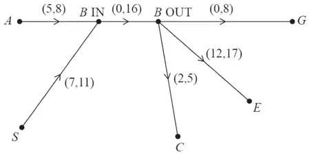 | B1 B1 | 3.3 3.3 |
| (ii) maximum flow = 40 | B1ft | 2.2a |
| (3) | ||
| (16 marks) |
Notes
B1: Flows into B go to BIN and flows out of B go from BOUT
B1: Arc of capacity 16 from BIN to BOUT
B1ft: value of their maximum flow – 3