
AS June 2024 Q1
1.
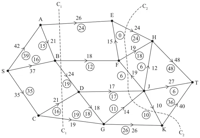
Figure 1 shows a capacitated, directed network of pipes. The number on each arc represents the capacity of the corresponding pipe. The numbers in circles represent a feasible flow from S to T.
The flow augmenting route in part (d) is applied to give an increased flow.
| Scheme | Marks | AO |
|---|---|---|
| Initial Flow = 90 | B1 | 1.1b |
| (1) |
Notes
B1: CAO
| Scheme | Marks | AO |
|---|---|---|
| The maximum flow into C is 35. Maximum flow in CD is 21 and maximum flow in CG is 19. 35 < 21 + 19 and therefore CD and CG cannot both be saturated | B1 | 2.4 |
| (1) |
Notes
B1: CAO (as a minimum accept: max inflow to C = 35 and max outflow = 40 and 35 <40)
| Scheme | Marks | AO |
|---|---|---|
| (i) 26+18+24+21+19 = 108 (ii) 24+19+17+14+40 = 114 | B1 B1 | 1.1b 1.1b |
| (2) |
Notes
(i) B1: CAO
(ii) B1: CAO
| Scheme | Marks | AO |
|---|---|---|
| SBFJT (+6) | B1 | 1.1b |
| (1) |
Notes
B1: Correct flow augmenting route found from S to T
| Scheme | Marks | AO |
|---|---|---|
| Use of max-flow min-cut theorem Identification of cut through EH EF BF DJ DG and CG Capacity of cut = 96 Therefore it follows that flow is maximal | M1 A1 A1 | 2.1 3.1a 2.2a |
| (3) | ||
| (8 marks) |
Notes
M1: Construct argument based on max-flow min-cut theorem (e.g. attempt to find a cut through saturated arcs) Cut must be drawn or listed as arcs not values (condone omission of EF for M1 only)
A1: Use appropriate process of finding a minimum cut (both cut and value correct)
A1: Correct deduction that the flow is maximal (dependent on previous A mark) (must use all four words Max Flow = Min Cut)